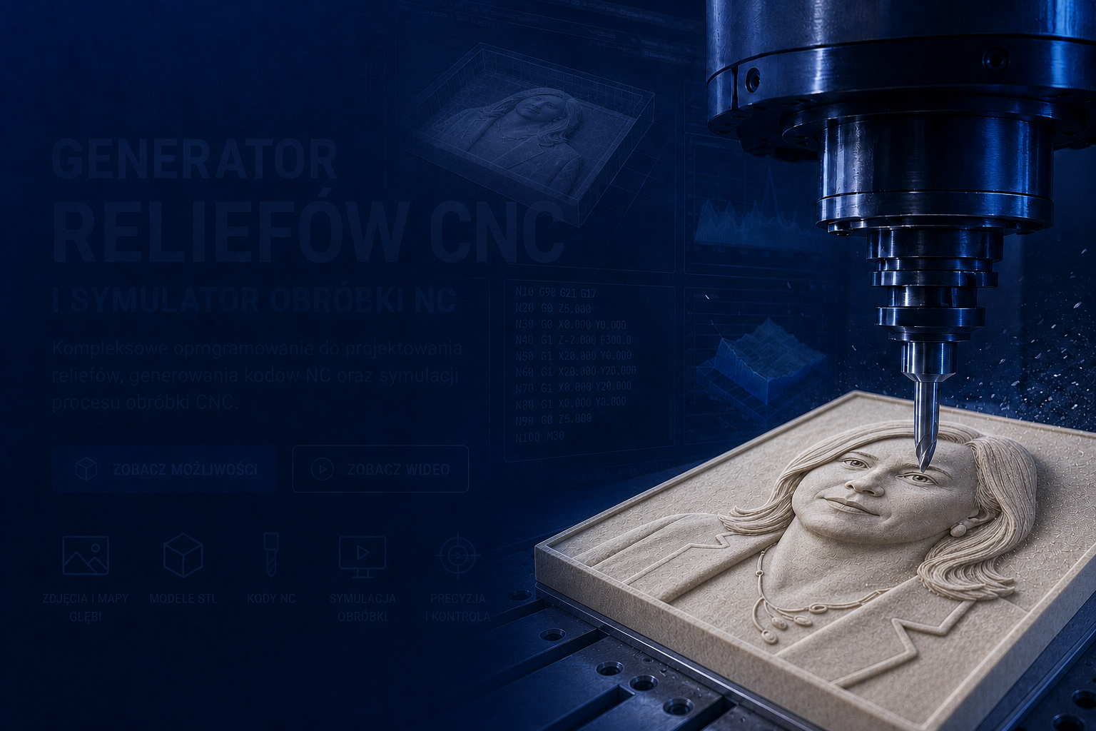
Relief Generator

CNC program package Generator, Simulator, SVG Studio and Studio NC

The website presents four tools supporting the preparation of work on CNC machines. The idea of ​​the package was that programs could be run directly in the browser, without installing additional software on the computer: Relief Generator creates models and NC codes, NC Machining Simulator allows you to check the program before starting the machine, SVG Studio is used to design and correct SVG files, and NC Studio generates CNC code from vector graphics.

Here you can run each program of the package immediately in the browser, without installation. Select the module you need now:

What do the programs included in the package offer?

The package combines four programs that together help you go from an idea or source graphic to a proven program for your CNC machine. The most important assumption was simple: the user was to enter the website and run the necessary tool in the browser, without installing any program, drivers or additional packages. You can prepare a relief from a photo, design a simple SVG graphic, convert the contours into G-code, and then check the processing in the simulator before starting the machine.

  • run programs directly in the browser, without installation on the computer,
  • create reliefs from photos, depth maps, height maps and STL models,
  • Design and enhance SVG files with layers, text, symbols and simple shapes
  • vectorize raster images and control the conversion result in a large preview,
  • generate NC programs for reliefs and G-code from SVG contours,
  • set material size, design position, depths, feeds and Z safe,
  • add a cutting rectangle when working with SVG files,
  • edit NC programs and check their progress in the simulator,
  • use the HTML help describing the functions of SVG Studio and Studio NC.

This means you don't have to treat each program separately. The generator prepares reliefs, SVG Studio organizes vector graphics, NC Studio converts SVG into machine code, and the NC Simulator allows you to view and control the processing before performing it on real material.

Four work modules

  • Relief Generator: photos, STL, depth maps and NC codes.
  • NC simulator: machining preview, cross-sections and program control.
  • SVG Studio: design, vectorization, layers, text and symbols.
  • SVG Studio CNC: G-code with SVG, engraving and cutting.

CNC Relief Generator

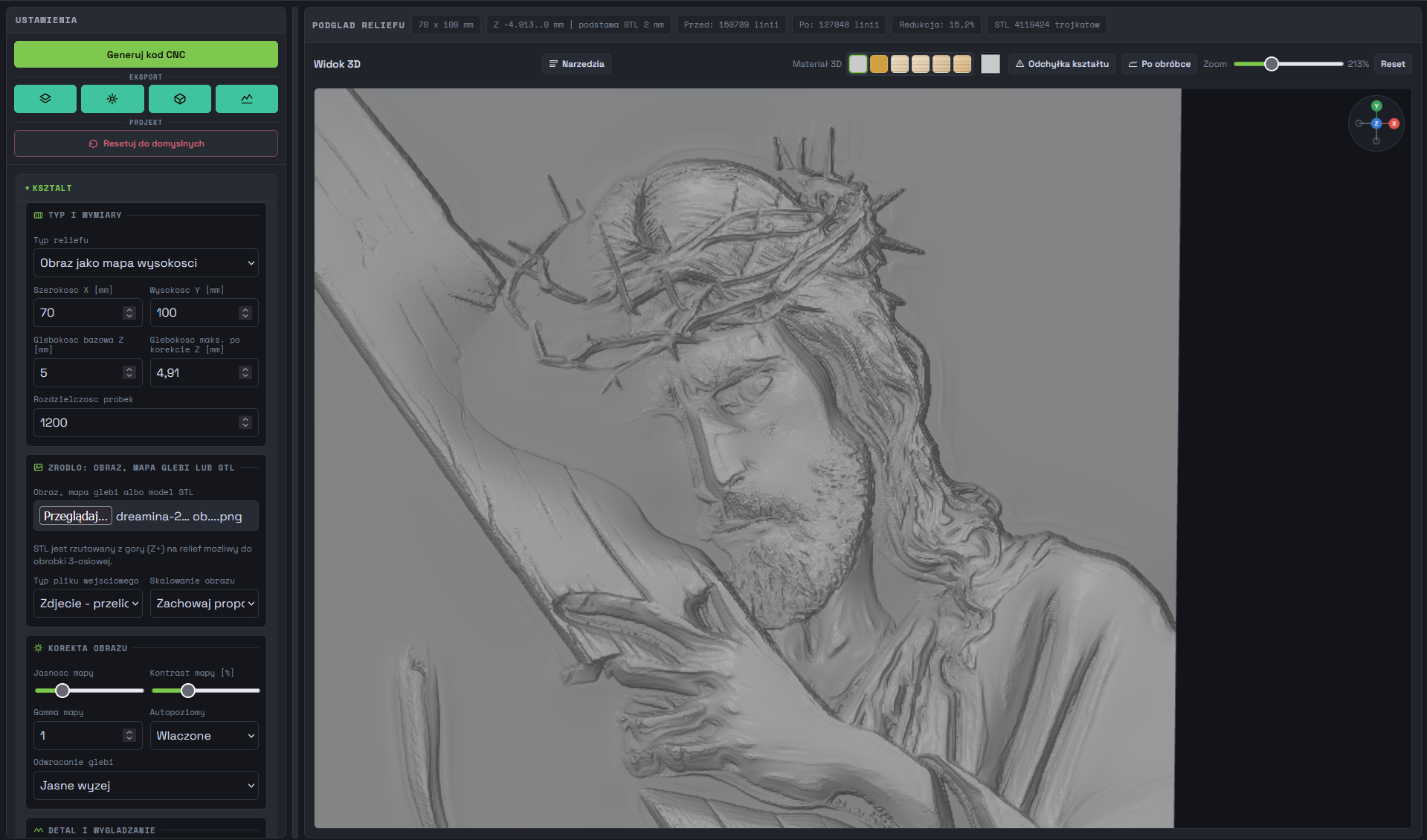
The program allows you to prepare reliefs for processing on CNC machines. Data can come from photographs, depth maps or STL models. Built-in tools allow you to prepare material for processing without the need to use external applications.

Generowanie kodów NC

Generating NC codes

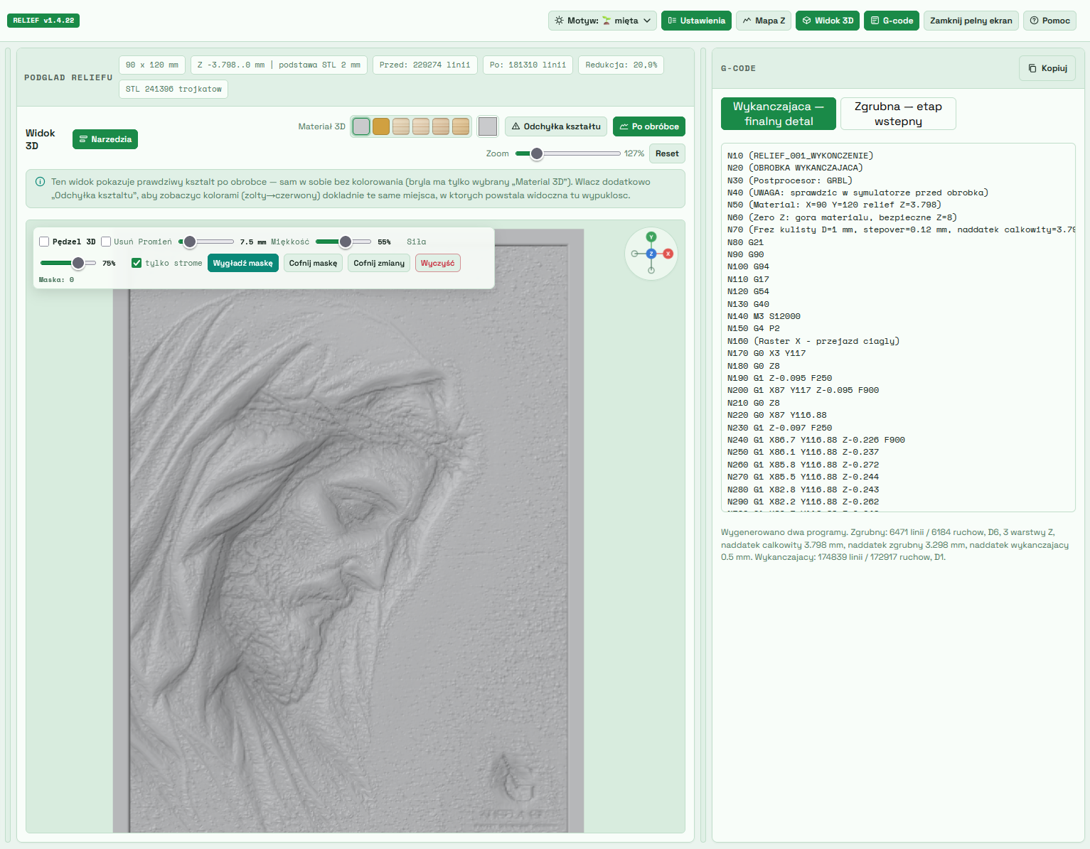
The generator automatically determines tool paths for reliefs made on CNC milling machines. It is possible to prepare programs for roughing and finishing using different cutter diameters.

  • automatic path generation,
  • selection of machining parameters,
  • support for many tools,
  • preview of the trajectory before saving the program.

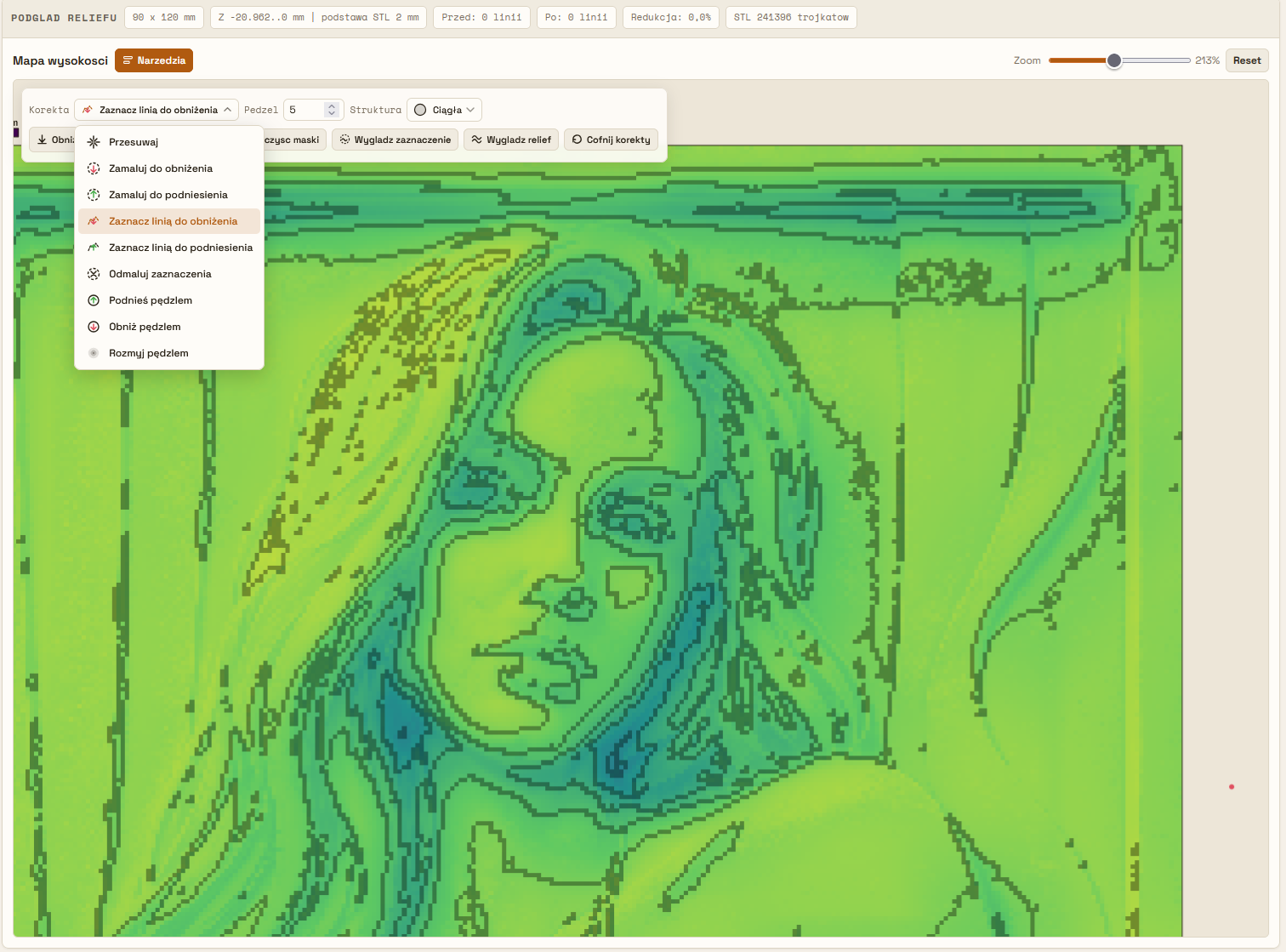
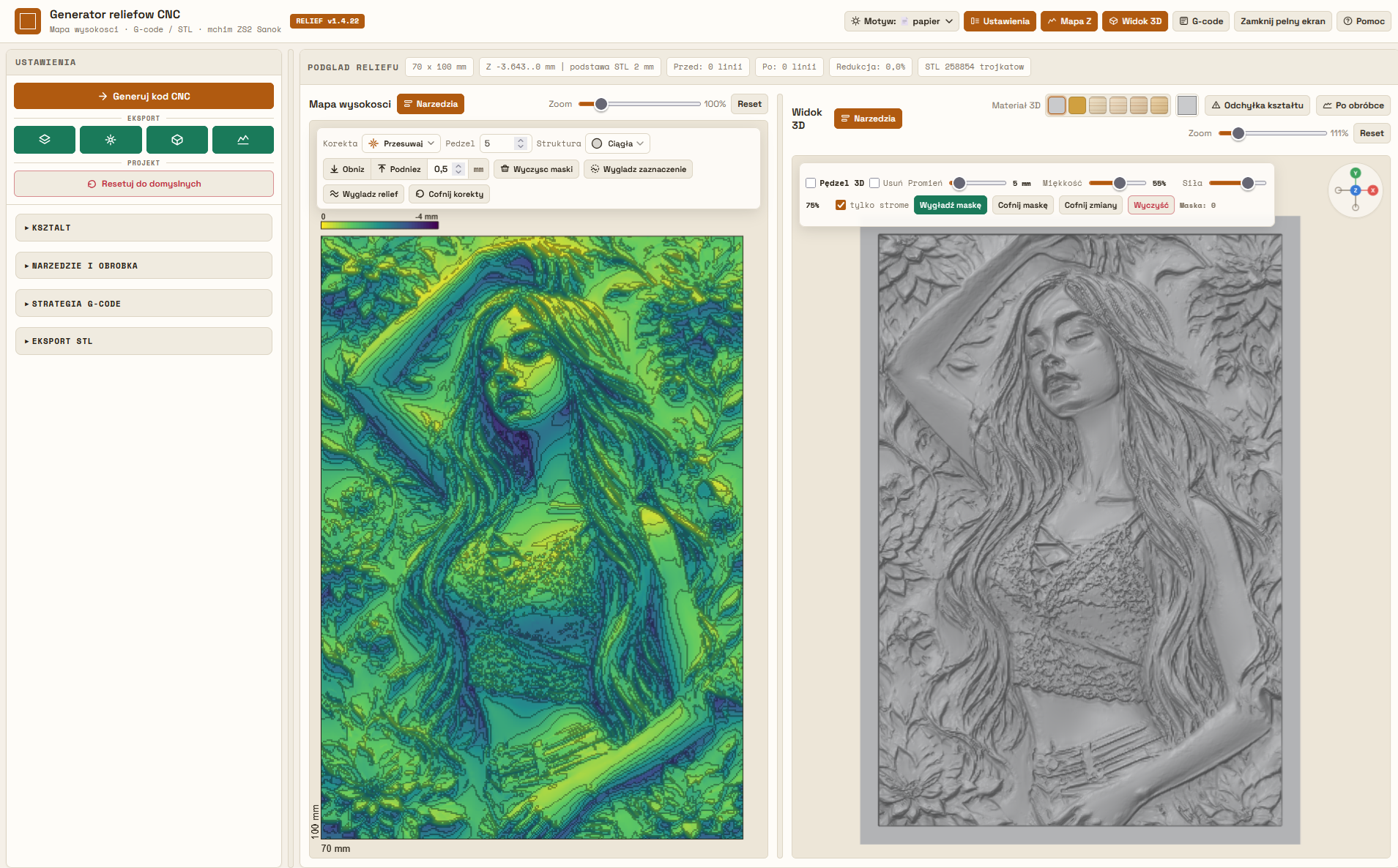
Height map correction

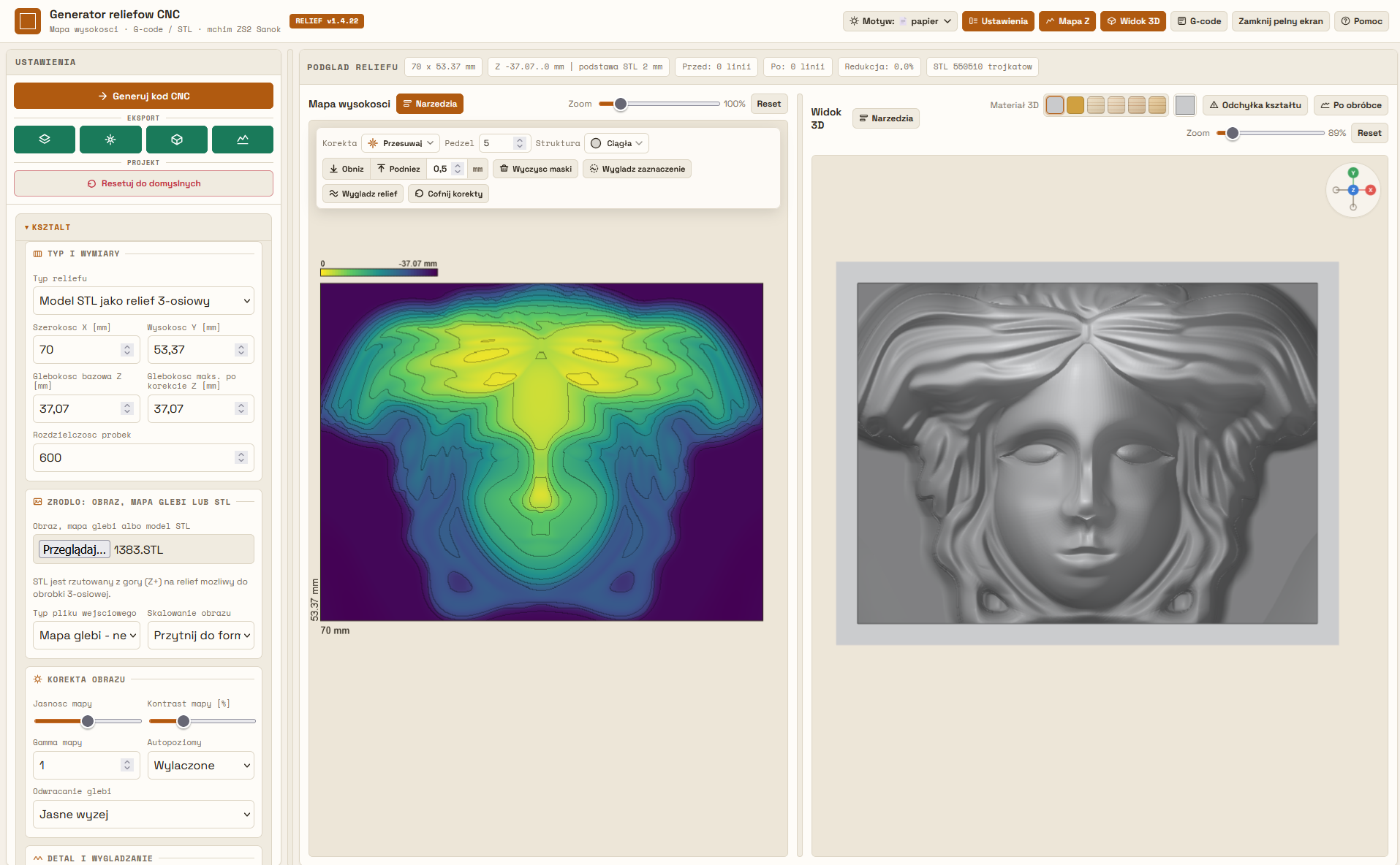
Before generating toolpaths, the height map can be freely modified. The program provides a set tools enabling local editing of selected fragments relief without the need to use an external program graphic.

  • drawing with a brush,
  • marking areas with lines,
  • local surface lifting,
  • local lowering of the surface,
  • height equalization,
  • smoothing transitions,
  • masking selected areas.
Korekcja mapy wysokości
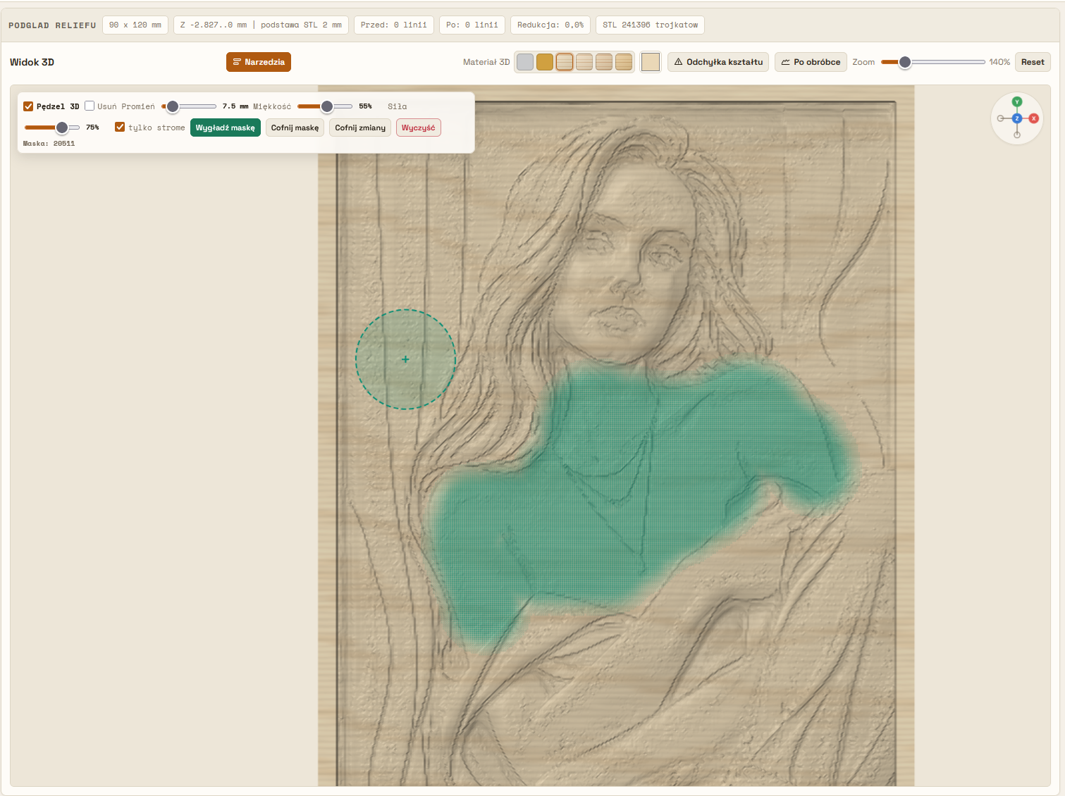
Wygładzanie reliefu

Direct relief editing

Once generated, the relief can be further processed directly in the program. This makes it possible removing imperfections and preparing the model exactly to the planned machining.

  • smoothing flat surfaces,
  • smoothing steep slopes,
  • automatic background removal,
  • manual background removal,
  • local detail correction,
  • elimination of artifacts,
  • improving the quality of the relief.

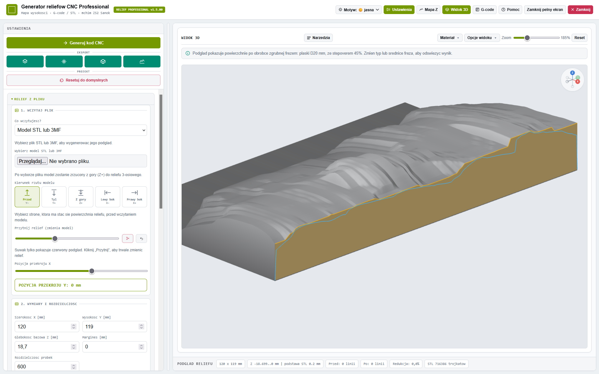
Import STL and 3MF models — project them into a relief

The generator imports 3D models in STL and 3MF formats and projects them onto a height map. Choose the front, back, top, left or right side of the model to become the relief surface. The visible heights from that direction are converted into a relief ready for 3-axis CNC machining.

  • import STL and 3MF models,
  • choose a projection direction: front, back, top, left or right side,
  • create a height map and relief from a 3D model,
  • set the X/Y dimensions and relief depth,
  • trim the relief to the required depth.
Obsługa STL
Ustawianie płaszczyzny przycięcia reliefu STL lub 3MF

Relief trimming and milling depth control

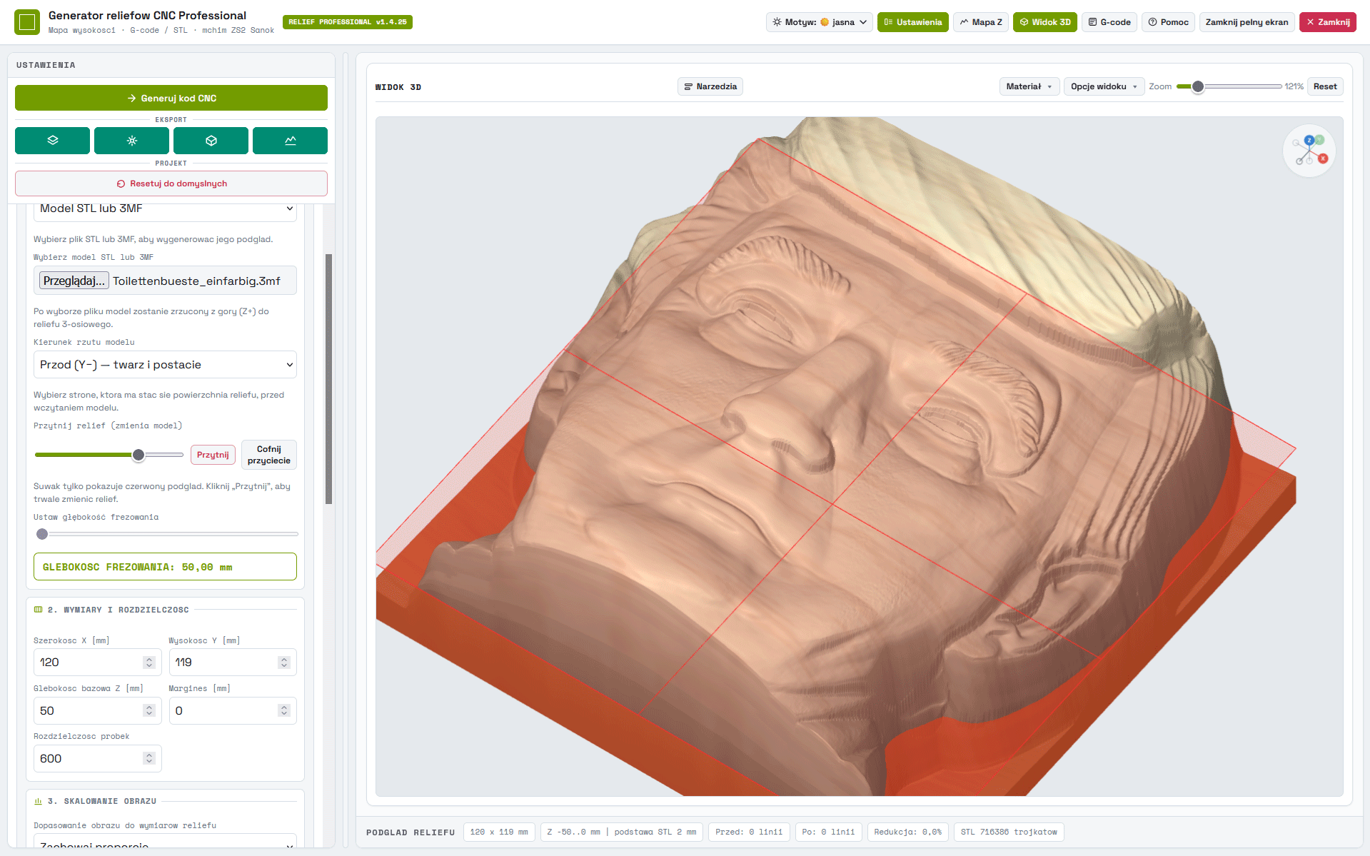
For STL and 3MF models and depth maps, you can limit the relief to the desired height. The red plane shows the trimming point, and once approved, the program creates a flat base.

  • permanent trimming of the relief to the indicated level,
  • undo the trim and return to full depth,
  • yellow reference plane for manual setting of the milling floor,
  • unambiguous maximum depth reading used in G-code.

Flat base after cutting

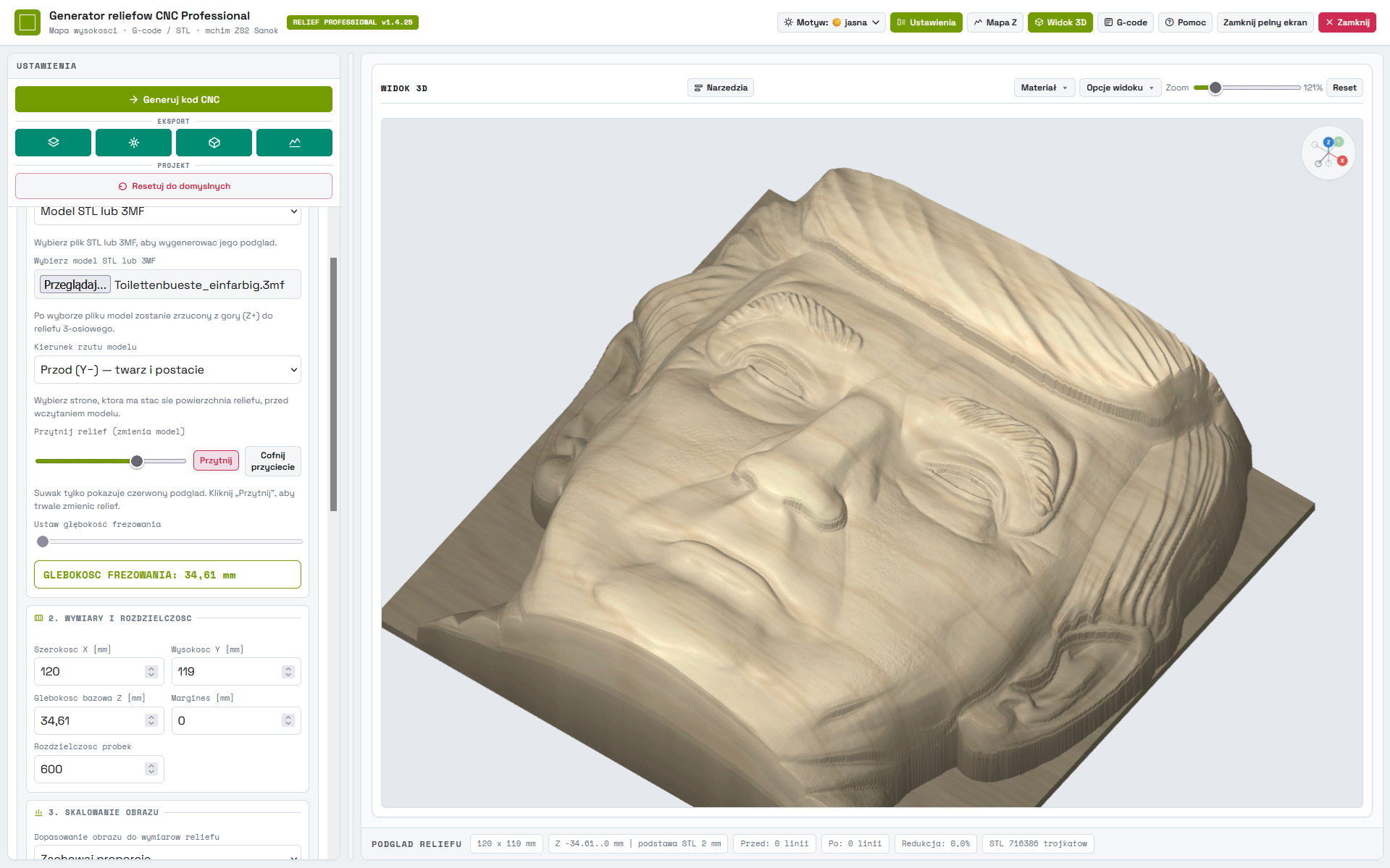
After confirming the cut, the part of the relief below the plane is leveled. This allows you to prepare relief plates for roughing and finishing without milling the full height of the original model.

Relief STL lub 3MF po przycięciu z płaską podstawą

Analysis of relief sections

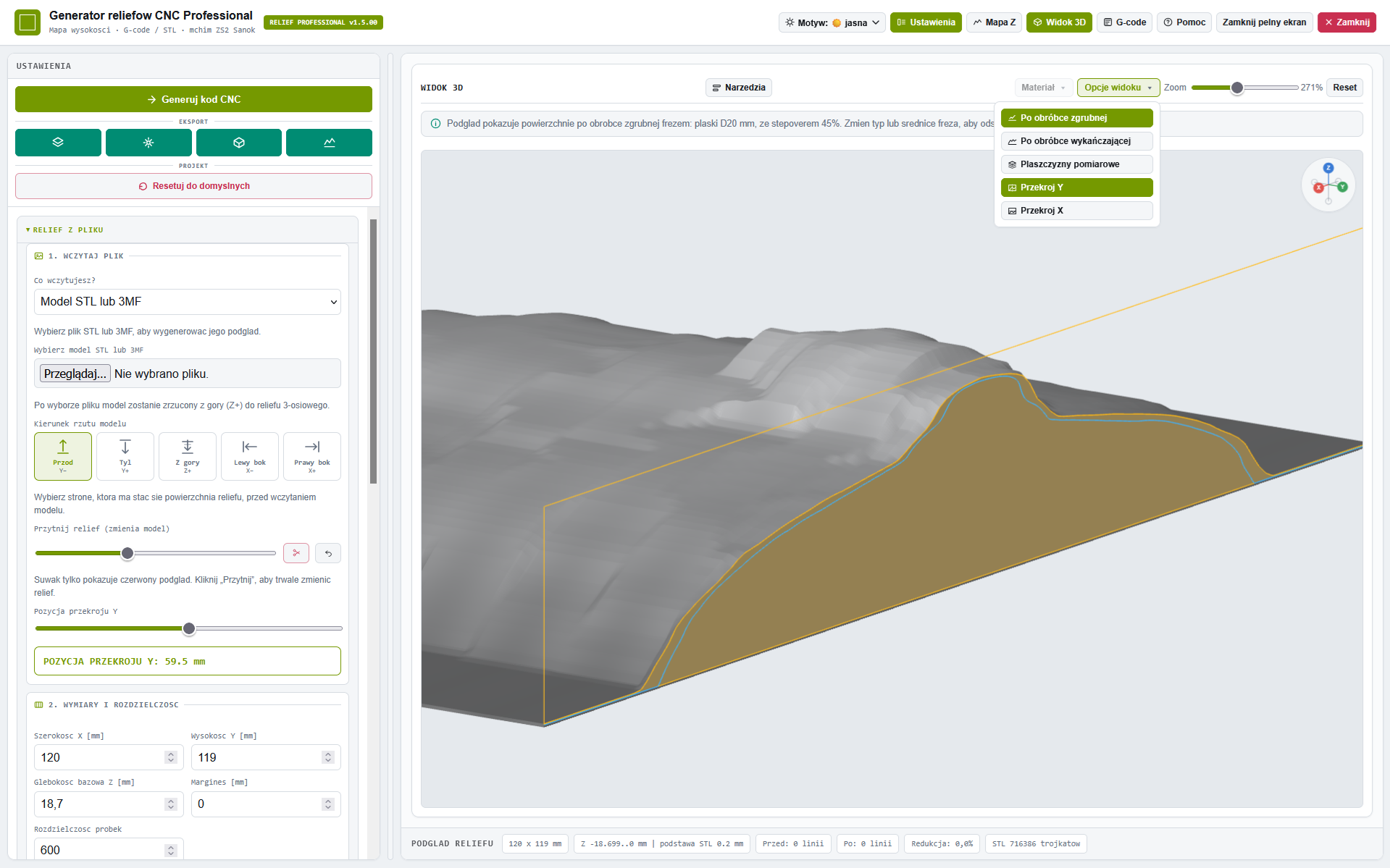
In the 3D View, you can move the section plane perpendicular to the X or Y axis.

The theoretical cross-section of the relief can be compared with real cross-sections after roughing and finishing. This makes it easy to check where the diameter and shape of the cutter limit the reproduction of the detail.

  • X-Z section, moved along the Y axis,
  • Y-Z section, moved along the X axis,
  • comparison of the theoretical profile with rough machining,
  • comparison of the theoretical profile with finishing machining.
Analiza przekroju reliefu prostopadłego do osi Y
Analiza przekroju reliefu prostopadłego do osi X

Checking for differences after milling

The colored outline shows the profile remaining after the selected processing step. Combining it with the theoretical profile allows you to select the cutter and transition parameters before creating an NC program.

Obróbka fotografii

Creating reliefs from photographs

The program allows you to prepare reliefs directly from photography. Built-in tools allow you to improve image before generating the height model.

  • brightness adjustment,
  • contrast adjustment,
  • level correction,
  • changing the relief depth,
  • real-time preview of effects.
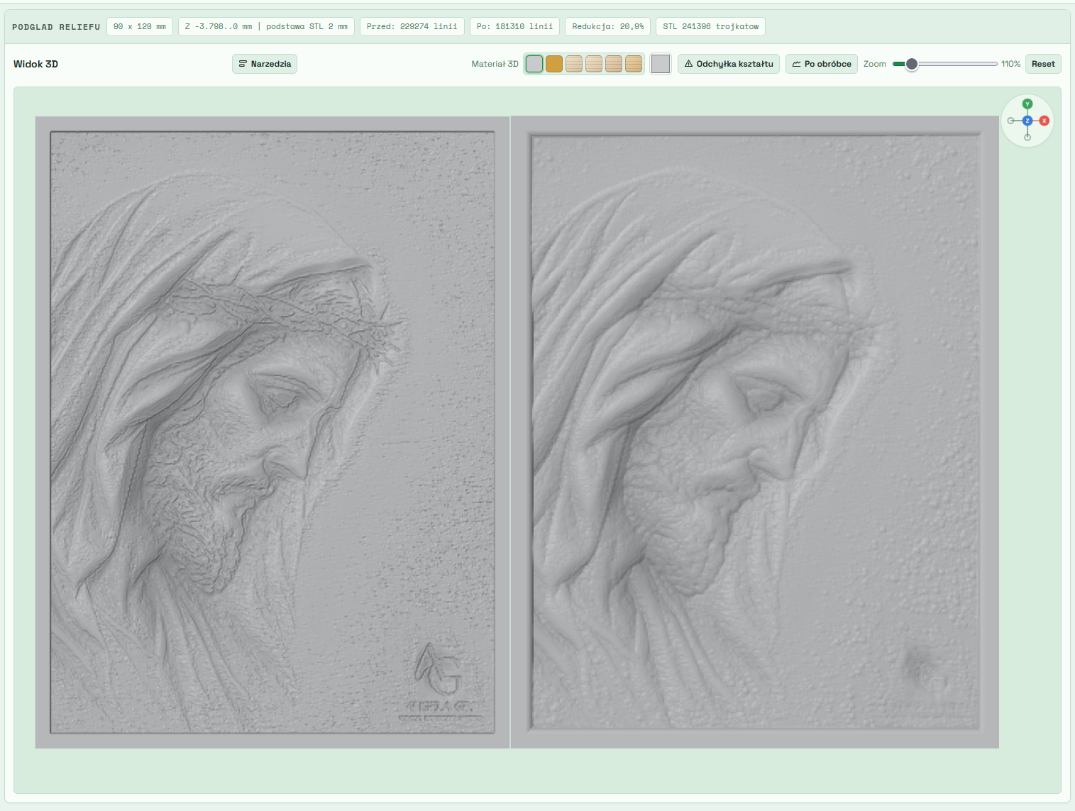
Relief teoretyczny i rzeczywisty

Theoretical and real relief

The program allows you to compare the ideal relief model with the expected processing effect obtained for the selected one cutter. This allows the user to evaluate the quality mappings before generating the NC code.

  • model comparison,
  • assessment of loss of detail,
  • surface quality analysis,
  • optimization of the machining process.

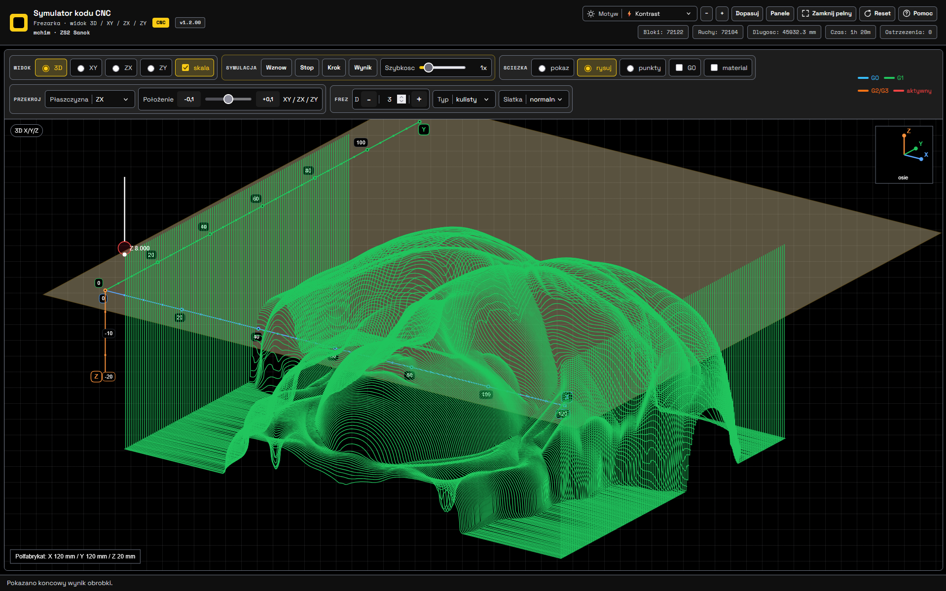
NC Machining Simulator

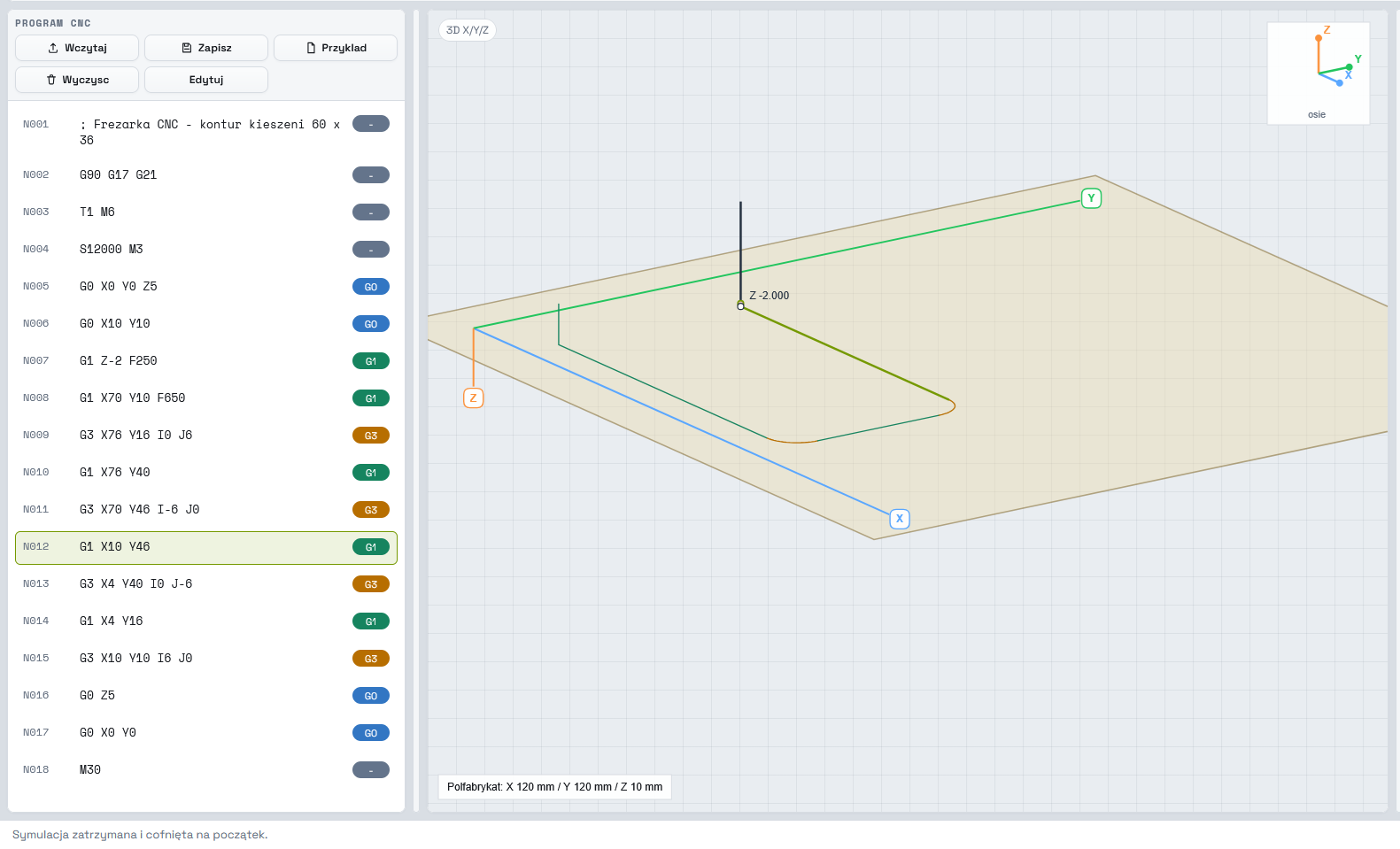
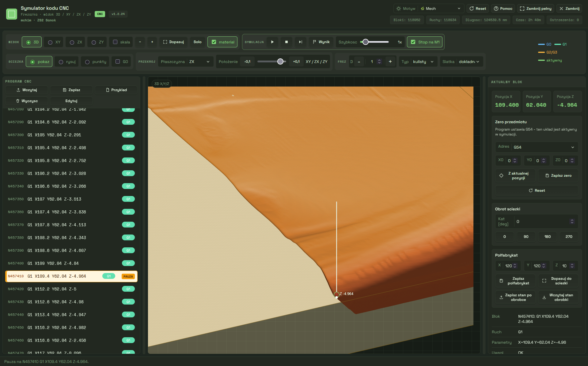
The simulator allows you to analyze the machining process even before starting the machine tool. The program can load existing ones NC programs or create new programs directly in the editor.

Edytor programów NC

Creating and editing NC programs

The program has a built-in editor that allows creating new programs and modifying existing ones existing NC codes.

  • creating NC programs,
  • editing existing programs,
  • block numbering,
  • quick line search,
  • highlighting the executed block,
  • support for standard G and M codes.

Two simulation modes

The simulation can be performed in two independent ways operating modes. The user can observe the movement tools or a changing semi-finished product.

  • tool path view,
  • view of the processed material,
  • switching views while working,
  • rotating the 3D model,
  • zooming and panning the view.
Dwa tryby symulacji
Symulacja krokowa

Automatic and stepwise simulation

The program allows you to perform full simulation automatic or block-by-block program analysis.

  • step start,
  • automatic simulation,
  • changing playback speed,
  • pausing the simulation,
  • return to the selected program point.

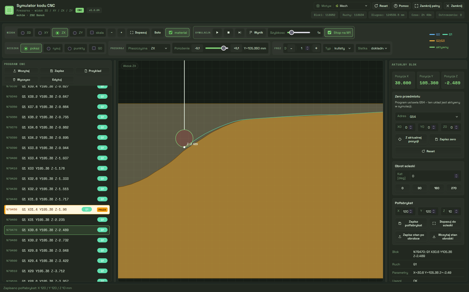
Cross-sectional analysis

You can analyze the processing result at any time in XY, XZ and YZ sections.

  • XY section,
  • XZ section,
  • YZ section,
  • measurement of processing depth,
  • control of the excess left.
Analiza przekroju
Duża rozdzielczość

Accurate representation of the material

The simulator allows you to work with high resolution sampling the material, making the simulation result faithfully reflects actual processing.

  • sampling up to 1200 × 1200,
  • precise surface analysis,
  • more faithful machining simulation,
  • greater accuracy of model comparison.

The most important capabilities of the simulator

✔ Loading NC programs
✔ Creation of new programs
✔ Editing NC codes
✔ Material simulation
✔ Tool path simulation
✔ Step simulation
✔ Automatic simulation
✔ XY Preview
✔ XZ Preview
✔ YZ Preview
✔ Save the blank
✔ Resuming machining after roughing

SVG Studio and SVG Studio CNC

SVG Studio and SVG Studio CNC modules today cover the entire simple vector graphics workflow: from image loading, vectorization and manual editing of the design, through layer control, to converting SVG into an NC program.

SVG Studio - edytor projektu SVG

SVG Studio

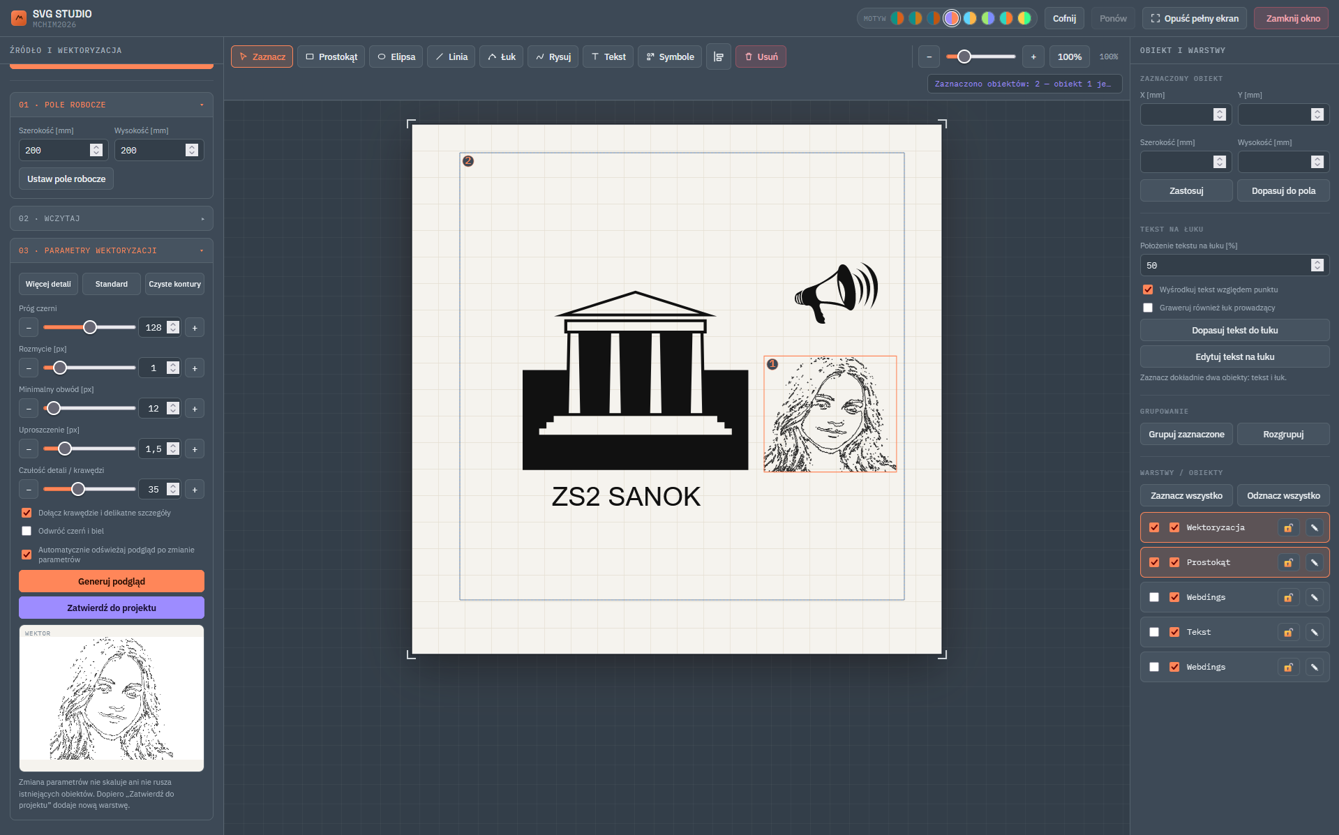
The program is used to prepare SVG vector designs. It allows you to load a raster or ready-made SVG image, transform the graphics into outlines, refine the result in a large preview, add your own elements, texts, symbols and simple shapes, and then organize the design in layers.

  • image vectorization into outlines with a large preview of the result,
  • adjustment of threshold, blur, simplification, detail sensitivity and line thickness,
  • loading ready-made SVG files as new layers,
  • drawing lines, rectangles, ellipses, arcs, polylines and your own paths,
  • adding text, text on an arc and symbols,
  • selecting multiple objects, moving a group, copying and pasting,
  • scaling, aligning, grouping, blocking and hiding objects,
  • a separate help file with a program map and enlarged screenshots,
  • saving the finished project to an SVG file.
SVG Studio CNC - generator G-code z SVG

SVG Studio CNC

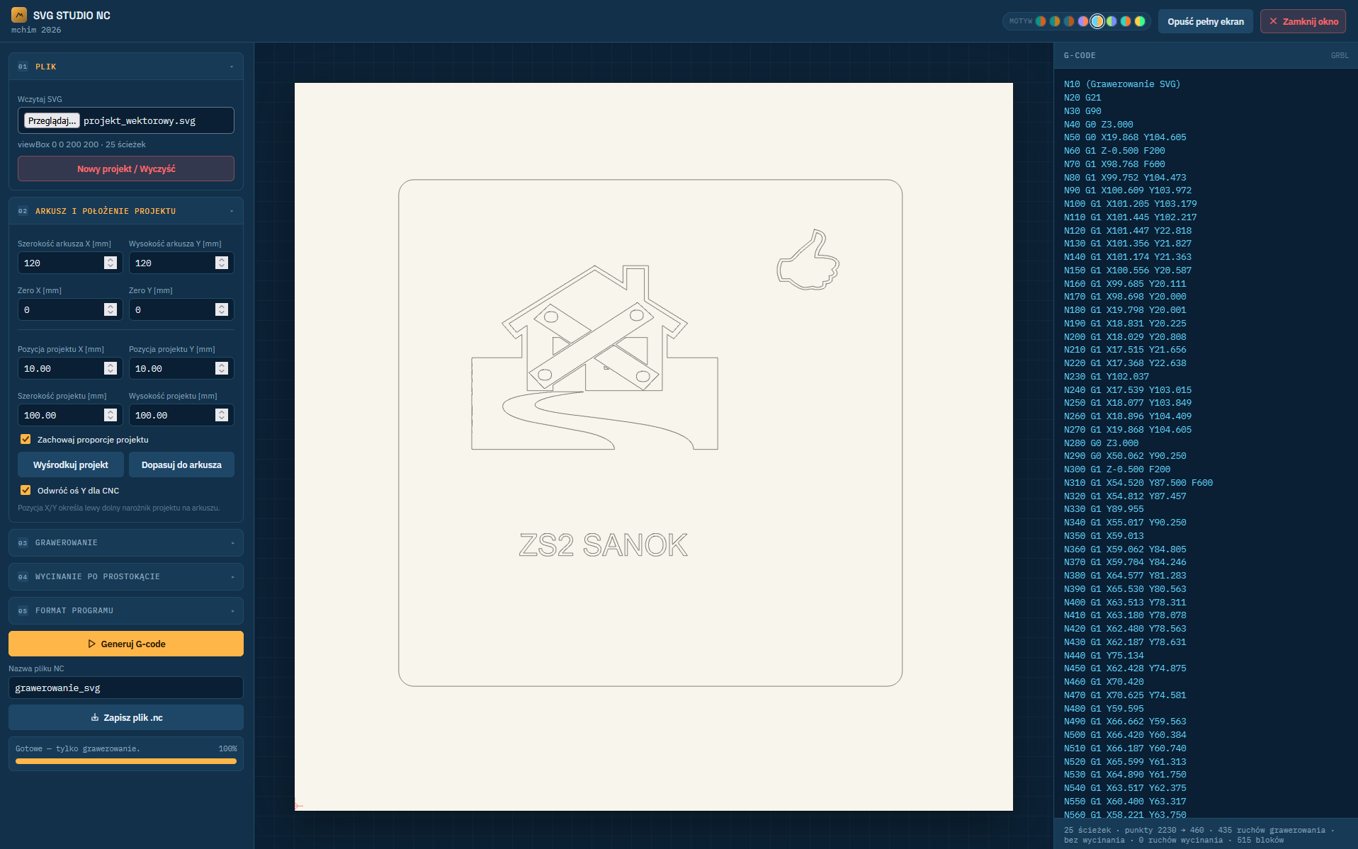
The program is used to convert a ready-made SVG file into a CNC machining program. It also reads vector paths from more complex files downloaded from the Internet, converts them into cutter movement, allows you to set dimensions, position, depth and feeds, and then generates NC code.

  • loading SVG files and previewing the design on the sheet,
  • safer conversion of foreign SVGs without crashing the program,
  • setting the sheet, scale, zero point and project position,
  • selection of depth Z, safe Z, feeds and tolerances for simplicity,
  • G-code generation for contour engraving,
  • optional addition of a cutting rectangle with transitions,
  • a separate help file describing the settings and workflow,
  • saving the finished .nc file.

Comparison of program capabilities

Function Relief Generator NC simulator SVG Studio SVG Studio CNC
Source photos and images ✔ — ✔ —
Depth maps and height maps ✔ — — —
STL models ✔ — — —
Editing reliefs ✔ — — —
SVG design and editing — — ✔ —
Image vectorization for contours — — ✔ —
Layers, text and simple shapes — — ✔ —
Copy, paste and work with multiple objects — — ✔ —
Large conversion preview and line thickness adjustment — — ✔ —
Generating NC codes ✔ — — ✔
G-code from SVG files — — — ✔
Loading complex SVG files more securely — — ✔ SVG import ✔
Separate HTML help files — — ✔ ✔
Setting depths, feeds and safe Z ✔ — — ✔
Editing NC programs — ✔ — —
Machining and tool path simulation — ✔ — —
XY/XZ/YZ sections — ✔ — —
Save the blank — ✔ — —
Saving the finished project file ✔ ✔ ✔SVG ✔NC